Introduction to configuring Splash#
This tutorial explains the basics to configuring Splash from the ground up, entirely from the Splash user interface. It covers the following:
configuring the video inputs and outputs
loading the assets (3D model, image, video, …)
saving/loading the configuration
To do this tutorial, you will need:
Splash installed on your computer
knowledge of how your display devices (screens, projectors) are configured
Note that the calibration process is not explained in this tutorial, please refer to the single projector and the multi projectors examples for details in this regard.
Since the goal of this tutorial is to get to know Splash, there is no need for a video projector when following this tutorial.
Create a new configuration#
In this section you will create a new configuration to work with. To create it, we will start from the default configuration and build on it:
run Splash
select the window containing the user interface
open the save configuration dialog using the File > Save configuration as… menu
navigate to where you want to save the file
enter a filename in the Filename field
press the Enter key to save the file.
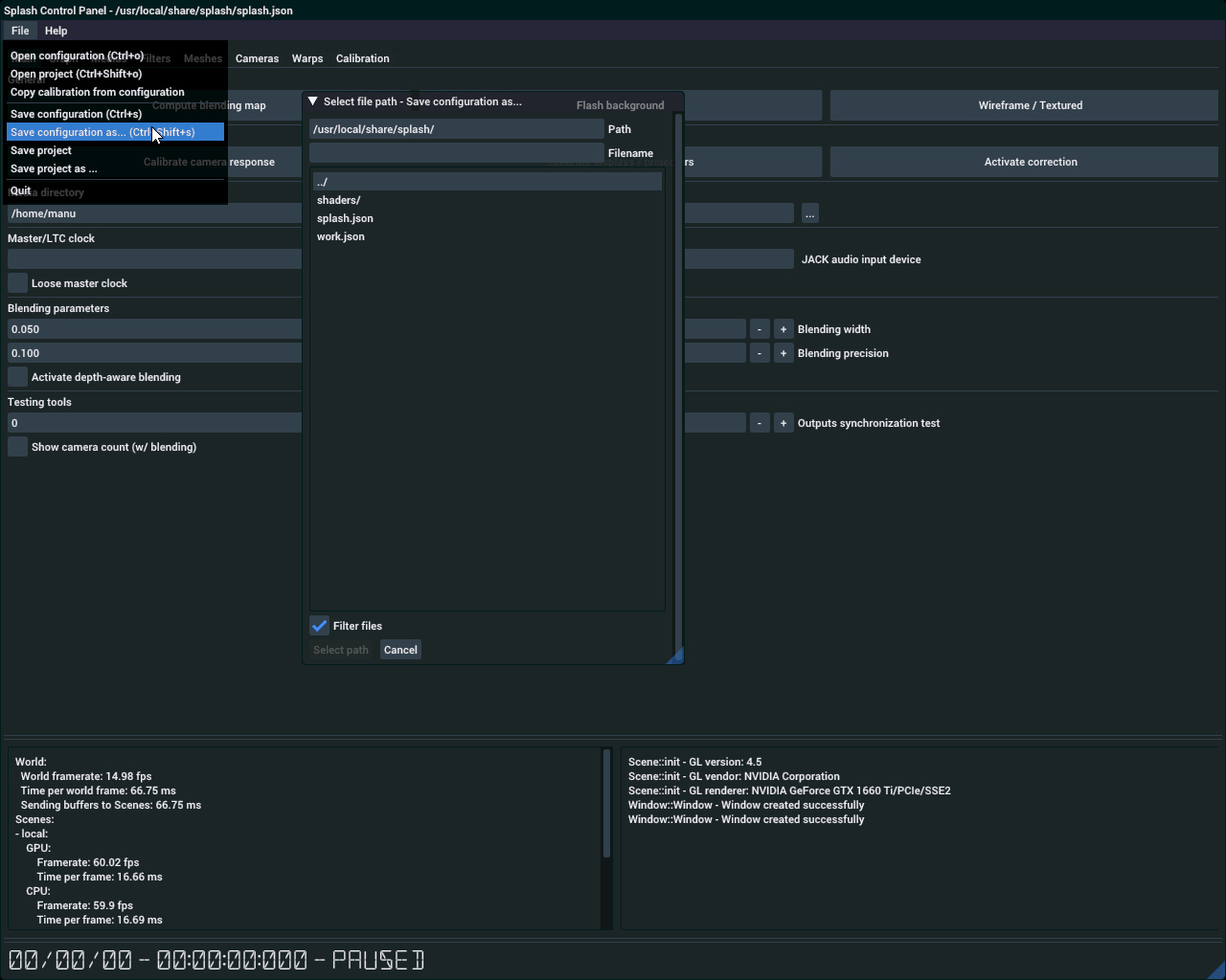
Save configuration as menu and dialog box#
Now reload the configuration:
show the open configuration dialog using the File > Open configuration menu
navigate to where the configuration file was previously saved
double click on the file to open it
You will notice that everything is black. That is because the asset files (for the mesh and the image) have not been copied along while saving the configuration to a new file. This will be taken care of in the following sections.
In the meantime, you can show the default mesh geometry by activating the wireframe view by clicking the Wireframe / Textured button in the user interface.
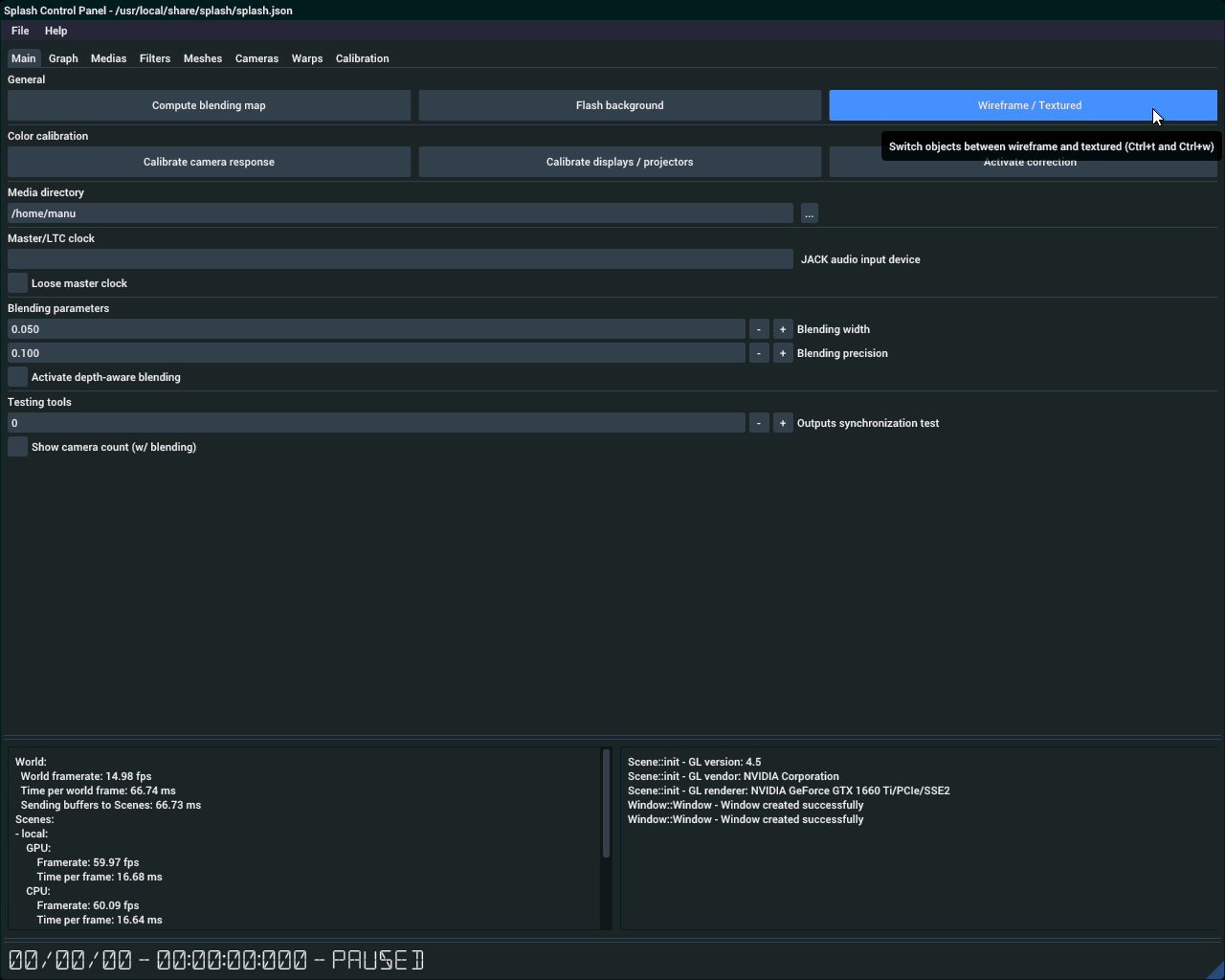
Set rendering to wireframe#
Navigate in the Graph tabulation#
We will learn how to navigate and control Splash’s scene graph through the UI Graph tab:
show the user interface by pressing Ctrl + Tab
click on the Graph tab to display the scene graph on the left side. The attributes for currently selected objects will be displayed on the right side.
click on the image node in the graph. Its attributes will now be shown on the right.
Now that the scene graph is visible, try moving around with these possible actions: - navigate in the graph by dragging it while holding the middle mouse button down, or by dragging it using the the right mouse button and holding down Alt. - move the nodes by dragging them using the left mouse button. - you can also select an object by looking for it in the Object list dropdown, under the scene graph.
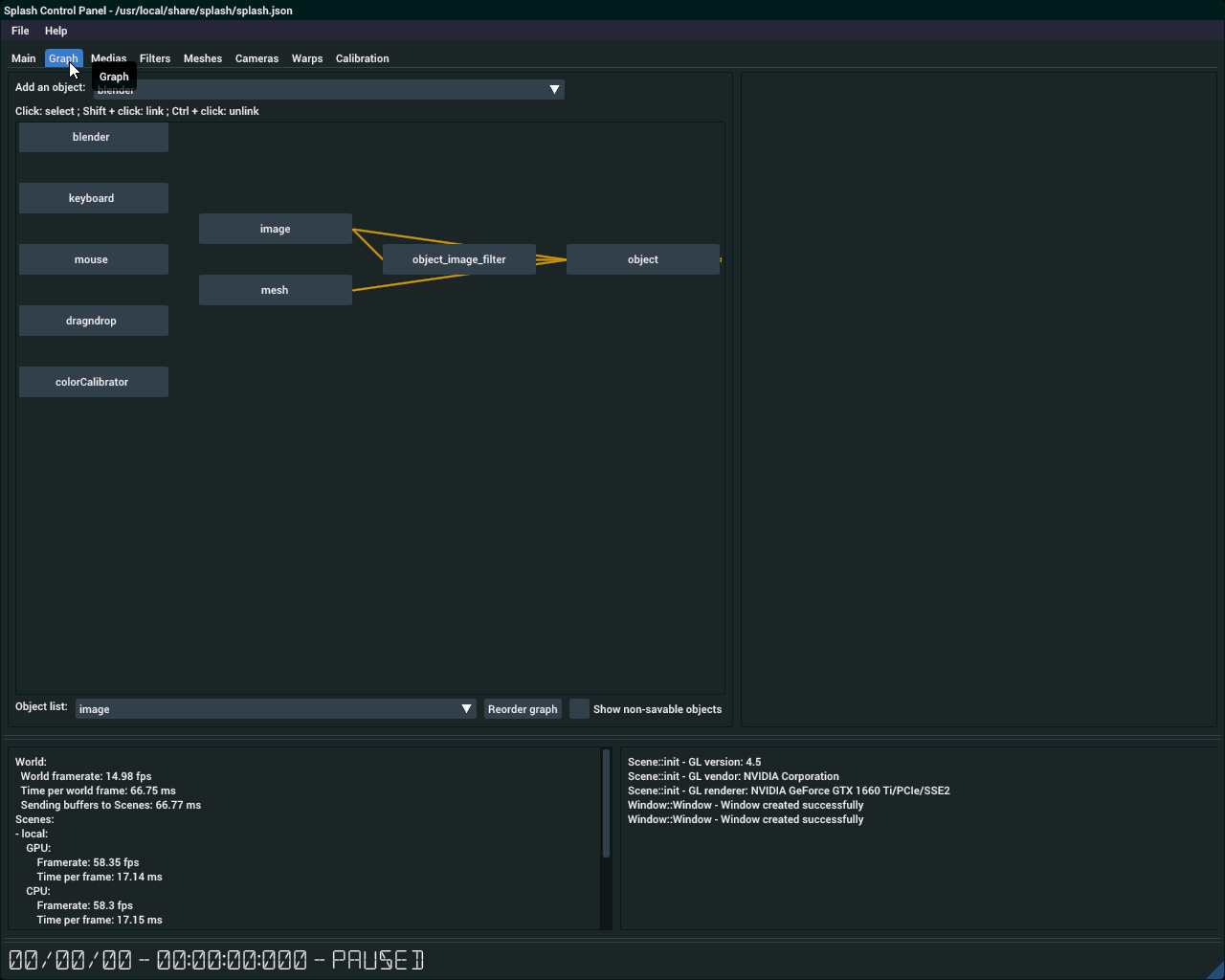
Graph tabulation for the default configuration#
Case study with two video projectors and one screen#
To continue this tutorial we will consider a simple case: a setup with one screen to show the user interface, and two video-projectors. The displays all have the same resolution of 1920x1080.
You need to configure your system such that all outputs are set next to each other. Since this step depends on the specific hardware used, we cannot cover for all cases. Here are two examples, one using the arandr tool and the other using nvidia-settings.
On the arandr configuration it would look like that:
Display configuration using arandr#
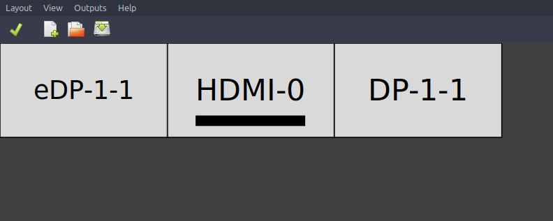
For NVIDIA hardware using the nvidia-settings tool, it would look like that:
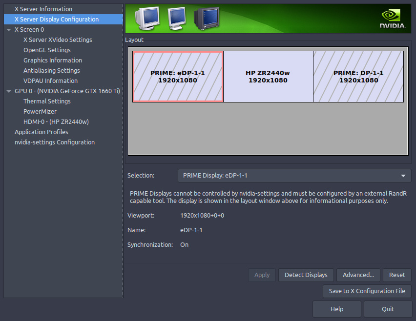
Display configuration using nvidia-settings#
Notice how all the displays are placed one next to another. In each case the first display is the screen, and the other two are the video projectors. Make sure that there is no gap between the displays.
Adapt Splash configuration to the hardware setup#
Here we will modify the previously-created Splash configuration to match this case-study.
In order to display the content that will be projected by the second video projector, we require a new camera:
first, create a camera by cliking on the camera option, located in the Add an object list above the graph. A new node named camera_1 will appear in the graph
select the new node by left-clicking on it
create a link between camera_1 and window_1 by Shift + left-clicking on the window_1 node
At this point, some nodes might overlap. To have a clearer view over the scene graph, you can press the Reorder graph button at the bottom of the scene graph.
Now let’s show something on the camera:
select the object node by left-clicking on it
with Shift pressed, left-click on camera_1 to create a link to it from the object node
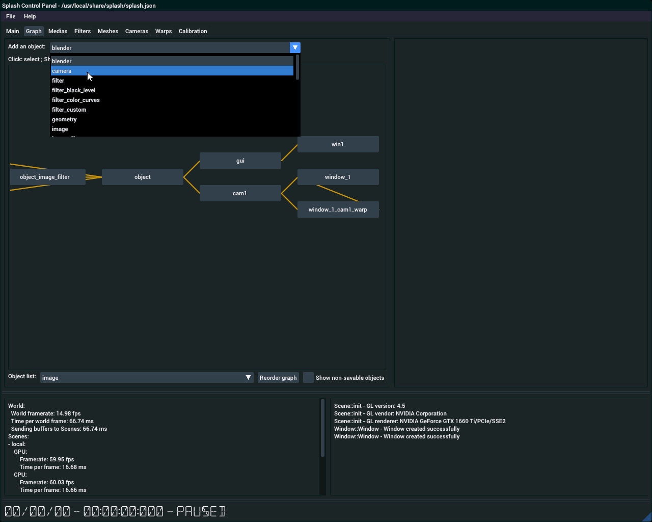
Drop down menu to add a window#
For now the window is not correctly located, and the cameras do not have the correct resolution:
select the window_1 node
change its size attribute to 3840 and 1080. It holds two 1920x1080 image, hence the 3840.
change its position attribute to 1920 and 0, considering your displays were configured as previously described.
select the cam1 node
change its size attribute to 1920 and 1080
select the camera_1 node
change its size attribute to 1920 and 1080
The scene graph should now look like this:
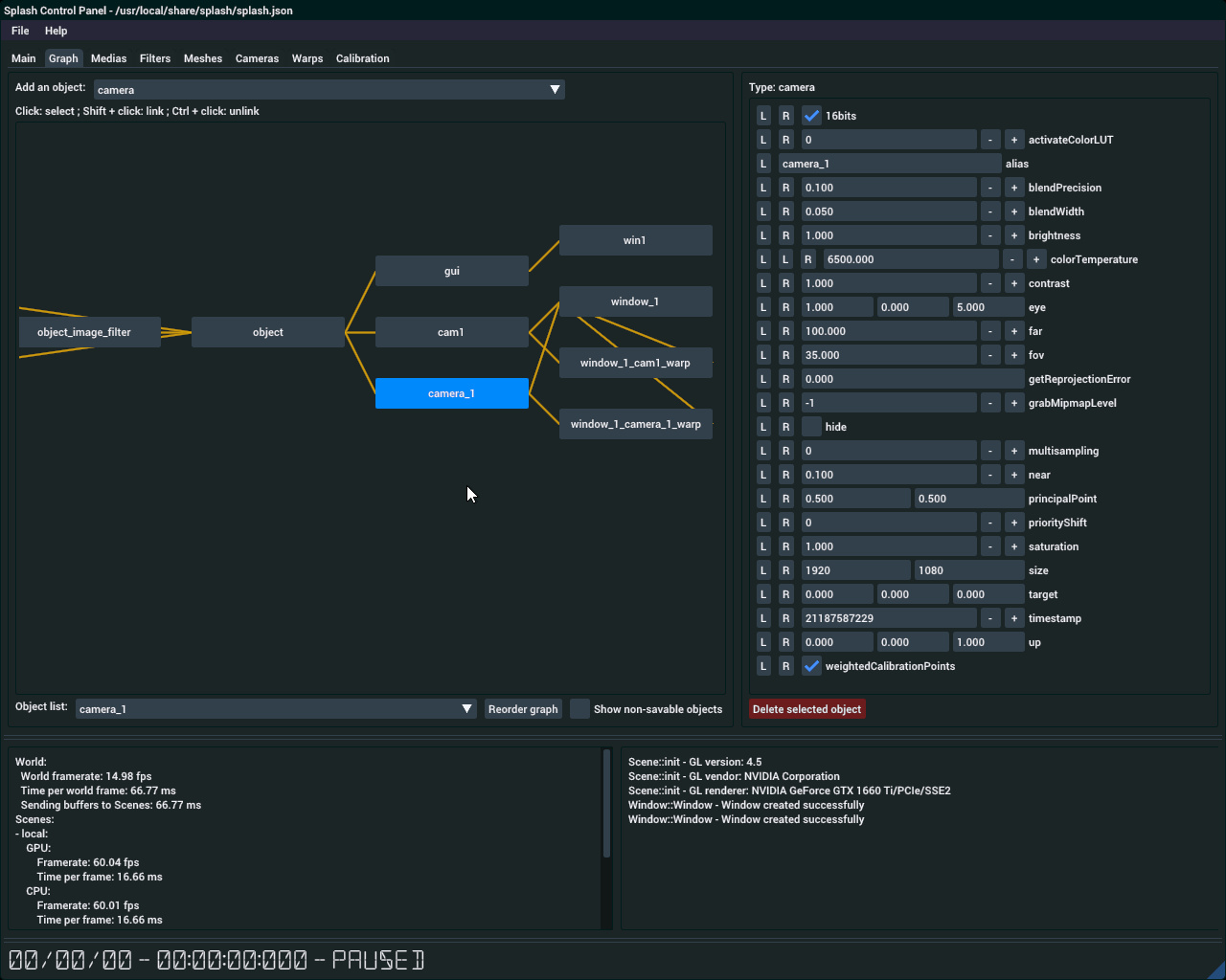
Resulting scene graph#
And the window_1 window should look more or less like this:
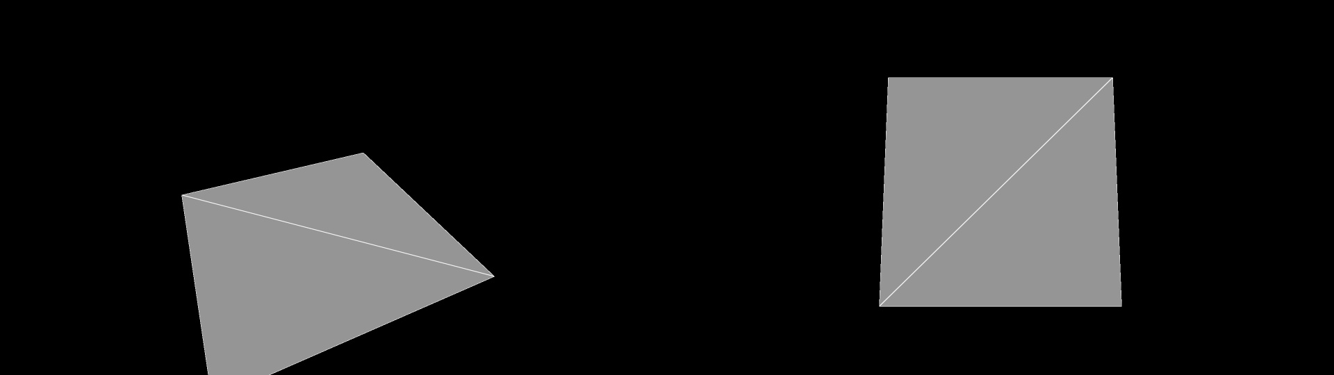
Resulting window for two projectors#
Select the 3D model and the visual input#
The configuration is mostly complete. Now what is needed is a 3D model of the projection surface, and a visual input to be shown. For that we will use the default assets accompanying Splash.
download the default assets from Splash repository: color_map.png and wall_corner.obj. Let say they were downloaded in the ~/Downloads directory.
go to the Medias tab. The image node attributes should be shown.
using the path attribute and its … button, open the file dialog and go to ~/Downloads. Double click on the color_map.png file to open it.
go to the Meshes tab. The mesh node attributes should be shown.
using the path attribute and its … button, open the file dialog and go to ~/Downloads. Double click on the wall_corner.obj file to open it.
You should now be capable of adapting the configuration to your needs. Next, you should go to the single projector example tutorial.