Multi-projector example#
This example explains step by step how to calibrate multiple projectors on a relatively simple surface. The projection surface is a tilted dome, projected onto with three video-projectors. The workflow is as follows:
create a low definition 3D model of the projection surface, used for calibration,
export from Blender a draft configuration file,
open the file in Splash, calibrate the video-projectors,
create a high definition 3D model of the projection surface, used for projection,
replace the low definition 3D model with the high definition one,
load some contents to play onto the surface.
To do this this tutorial, you will need:
Splash installed on a computer
at least two video-projectors connected to the computer
a non-planar projection surface, simple enough to be able to create a 3D model for it
Create a low definition (calibration) 3D model of the object#
The reason why a low definition 3D model is needed comes from how Splash handles video-projectors calibration. Basically, the idea is to tell Splash where a point of the 3D model should be projected onto the projection surface. Splash needs at least six points to be specified for the calibration process to run.
The thing is that it is easier to work with a very simple 3D model containing only the points for which we know precisely the position of the projection. These points can be taken as the intersections of edges, seams, or any point measured onto the surface. Using these points, a very basic 3D model is created and will be used throughout the calibration process.
Back to our case, the projection surface is a tilted dome made from glass fiber, with visible seams. The 3D model will contain only the points visible as the intersections of seams. In this case it will be enough for a correct calibration because each video-projectors covers a large portion of the dome, it may not be enough for other configurations. If we chose to go for five video-projectors instead of three, we may have had to place additional points onto the surface.
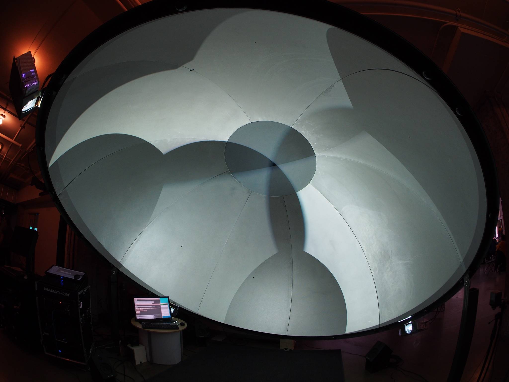
Dome uncalibrated - full white#
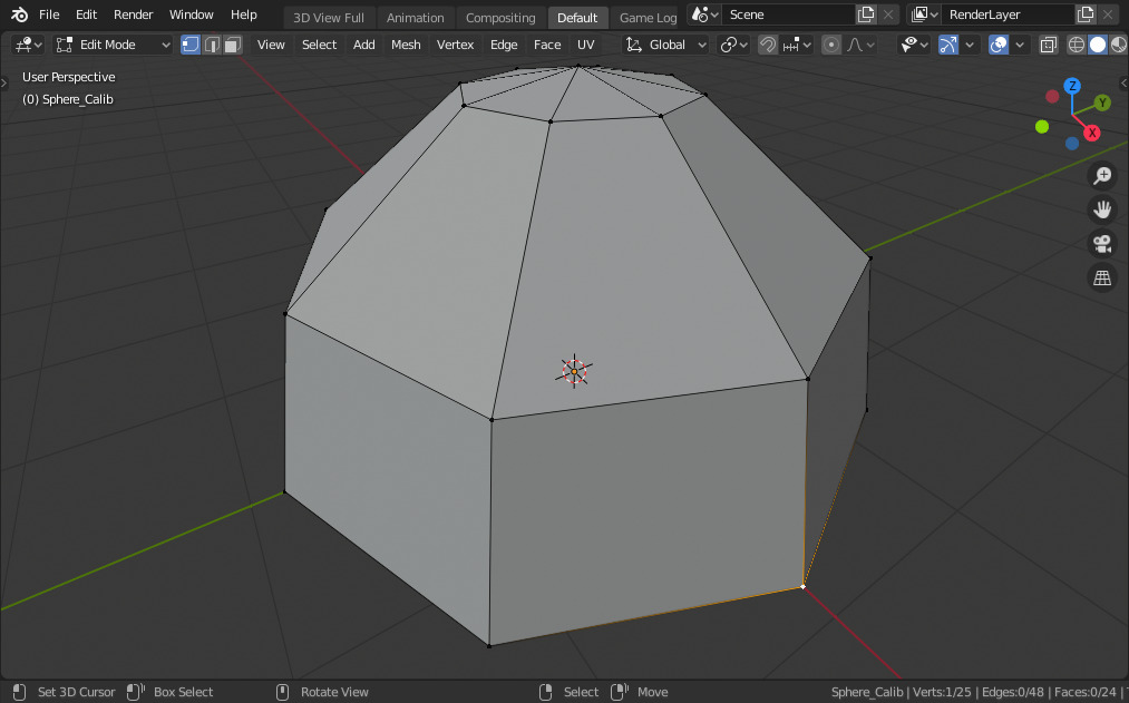
Dome calibration 3D model#
Finally, we need some texture coordinates to be able to display a pattern image and help with the calibration process. With the 3D model selected in Blender, enter Edit mode by pressing the Tab key, then press ‘U’ and select ‘Smart UV Project’. Then exit edit mode by pressing the Tab key again.
In the next sections, this low definition 3D model will be referred to as the calibration model.
Create the configuration using the Blender addon#
For this tutorial, we will create the configuration inside Blender. Note that it could very well be created entirely inside Splash. Please see the introduction to configuring Splash and the single projector example for some insight in this regard. The main difference would be the need for three cameras instead of two.
Back to Blender, now that we have the calibration model we can go forward with the creation of the base configuration for Splash, inside the same Blender project. For this example, we will consider that there are three video-projectors connected to the second, third and fourth outputs of the (only) graphic card. This first output is sent to an additional display for controlling purpose. All outputs are set to 1920x1080.
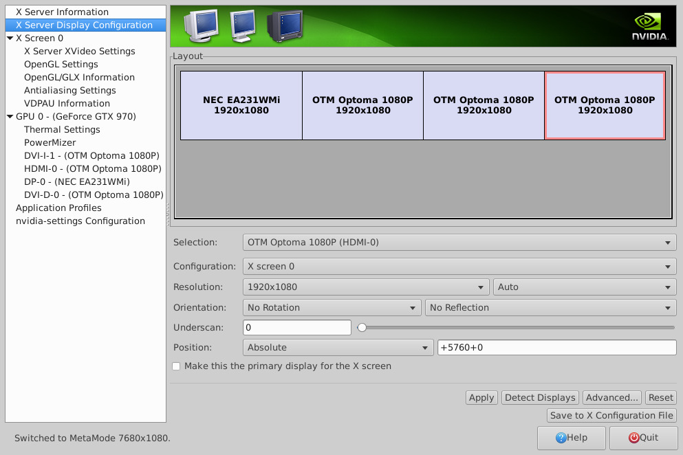
Output configuration#
The Splash addon for blender is used to create this configuration, the final Splash tree looks like this:
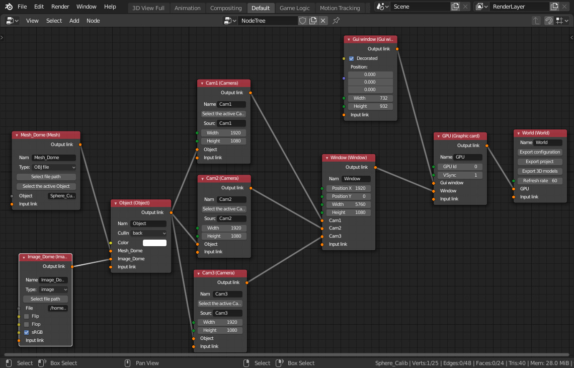
Splash Blender tree#
The tree must be read from right to left. The base node is the World one, to which all other nodes must be connected (directly or indirectly). A GPU node is connected to it, which represents the graphic card of the computer. If we had two graphic cards, we would have to create two of these nodes to output on all the available outputs.
The GUI window is created in a dedicated node, and will be displayed in the first monitor. There is only one other window, spanning accross all the video-projectors (hence its size of 3840x1080), and all cameras (each one corresponding to a video-projector) are connected to it. This is the advised set-up, as it leads to better performances. Overall, the fewer windows the better as it reduces the number of context switching for the graphic card.
An Object node is connected to all cameras as all video-projectors
target the same projection surface. This node receives as input an Image
node (which is set up to use the image located in data/color_map.png
inside the Splash sources), and a Mesh node node which is set to use the
data from the calibration model we created earlier, by typing the
calibration model name in the ‘Object’ field of the Mesh node. Please
note that the Object node has its ‘Culling’ parameter set to ‘back’, as
we want to project inside the dome.
Now we can export the Splash configuration by clicking on ‘Export
configuration’ on the World node, which will export all the nodes
connected to it. Let’s name the output file configuration.json. The
calibration model will be automatically exported in the same directory
as the configuration file, as its name has been entered in the Mesh
node.
Calibrate the multiple video-projectors#
Here comes the exciting part, the calibration of the video-projectors.
Load the newly exported calibration filer, either by running Splash and
drag&dropping the file calibration.json, or by launching Splash from
the command line with the configuration file as a parameter:
cd CONFIGURATION_FILE_OUTPUT_DIRECTORY
splash configuration.json
Two windows will appear. One is the GUI and shows up on the monitor, the other window spans accross all the video-projectors. If not, something is wrong with either the configuration in the Blender file, or with the configuration of the displays. If all is good, you should not have to interact with the second window at any time, everything is done through the GUI window.
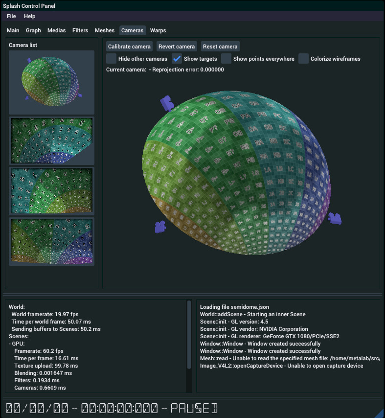
Splash GUI with multiview configuration#
General information about calibration#
Select the GUI window and press Ctrl+Tab: the GUI shows up! You can find additional information about the GUI in the Getting to know the user interface page. The important tabulation for now is named ‘Cameras’. Open it by clicking on it. From this tabulation you can select any of the cameras defined earlier in Blender. Note that when a camera is selected, it is highlighted by an orange seam, so as to help seeing to which video-projector this camera’s output is sent. By default the first camera from the list is selected, which is kind of an overview camera and is not sent anywhere. You have to go back to selecting this camera to disable any highlighting of the other cameras.
Once you have selected a camera, you can move the point of view with the following actions:
right click: rotates the view around
shift + right click: pans the view
ctrl + right click: zoom in / out
You can also hide other cameras to focus on one or two cameras with the following options:
Hide other cameras (or H key while hovering the view): hide all cameras except the selected one
Ctrl + left click on a camera in the list: hide / show the given camera
Now press Ctrl+W: this switches the view to wireframe mode. Ctrl+T switches back to textured mode. While in wireframe mode, you can see the vertices which will be used for the calibration process. Before starting with the calibration of the first camera, here is the general workflow for each camera:
select a vertex on the mesh by clicking on it,
the selected vertex now has a small sphere surrounding it, and a cross appeared in the middle of the view,
move the cross by left clicking in the view while holding Shift: this specifies to Splash where the selected vertex should be projected,
the cross can be moved precisely with the arrow keys,
repeat this for the next vertex. If you select the wrong vertex, you can delete the selection by left clicking on it while pressing Ctrl,
a vertex can be updated by re-selecting it,
it is possible to show all crosses by pressing A when hovering the view (or clicking on ‘Show targets’)
Once at least six vertices have been set this way, you can ask for Splash to calibrate the camera: click on the ‘Calibrate camera’ button (or press C while hovering the camera view). If the calibration is feasable, you should now see the calibrated vertices projected onto their associated cross. If the view did not change, it means that the calibration cannot be done and that no camera parameters can make all vertices match their cross.
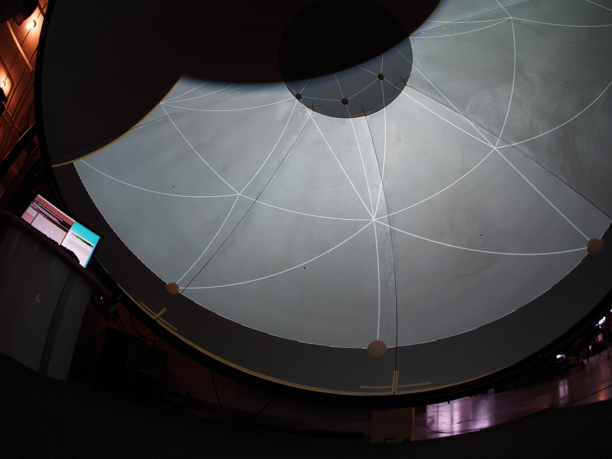
First projector, before calibration#
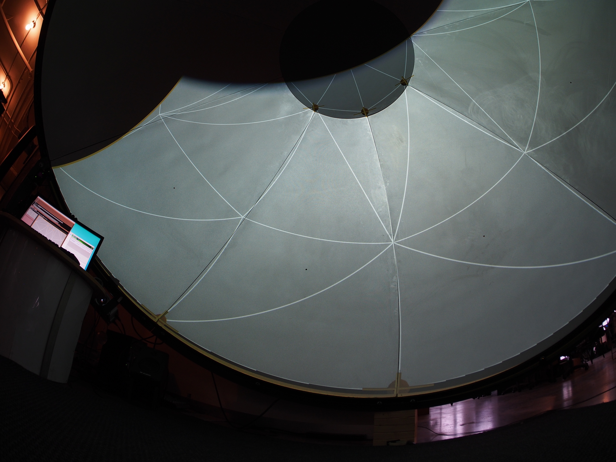
First projector, after calibration#
Calibration!#
We are now ready to calibrate all three video-projectors. Some general thoughts to begin with: the projection surface is a dome, which means that it has quite a few symetries. This allows us to start however we want. This would obviously not be the case with a non-symetrical object, like a room for example. Having that many symetries can also be a hurdle: once the first camera has been calibrated, it is not possible to calibrate the next camera without referring to the texture. With a non-symetrical object, the 3D model should be enough.
Back to calibrating the first camera. Using the workflow described earlier, calibrate the first camera by setting at least six calibration points. It is not advised to do any fine-tuning for now: first, the 3D model used for calibration is too low resolution for any meaningful assessment of the calibration quality to be made; second, the best thing is to do a first calibration pass on all video-projectors before doing any fine-tuning.

First projector calibrated#
Now for the second camera, we need to calibrate it so that its related projection matches the one of the first camera. This is where the calibration texture becomes useful. Switch to textured mode (Ctrl+T), then select in the Cameras tabulation the second camera. To make things clearer, deactivate the third camera by Ctrl + left clicking on it in the camera list.
In the camera view, move the camera around (right click, alone or with shift or ctrl pressed), and make it match the projection of the first camera (roughly). Switch back and forth between textured and wireframe mode to determine the correspondance between both cameras. Once you found a vertex displayed by both of them, select and calibrate it. From there, go on calibrating at least 5 other points.
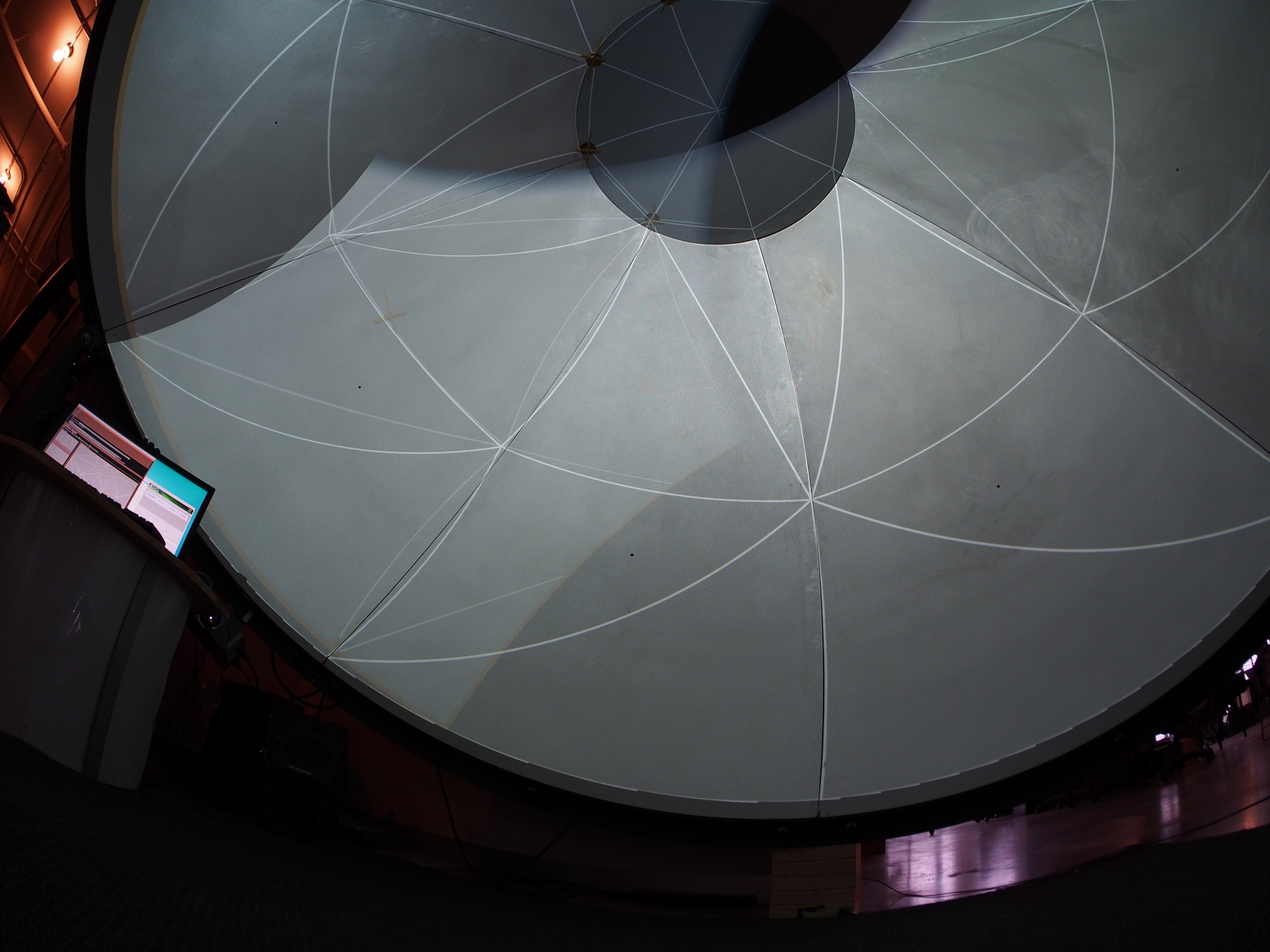
Second projector calibrated#
You can now go on to the third camera. Select it in the camera list: as soon as it is selected, the camera visibility is reset for all of them. Hide the second camera by Ctrl + left clicking on it, and proceed as for the second camera to calibrate it.
The first pass of calibration is finished, the next step would be to check the result, but for this we need a higher definition 3D model of our projection surface. Save the configuration by pressing Ctrl+S.
Create a high definition 3D model, and replace the low definition one#
There are multiples ways to create a high definition 3D model of a projection surface. As we are projecting onto a dome, we only need to create a UV sphere that we will cut in half. The only prerequisite is that its diameter is precisely the same as the diameter of the calibration model. We also need to generate the texture coordinates. To make it match a spherical projection, do as follows:
enter edit mode by pressing the Tab key,
select all vertices (using the A key),
press U, then chose ‘Unwrap’
exit edit mode by pressing the Tab key.
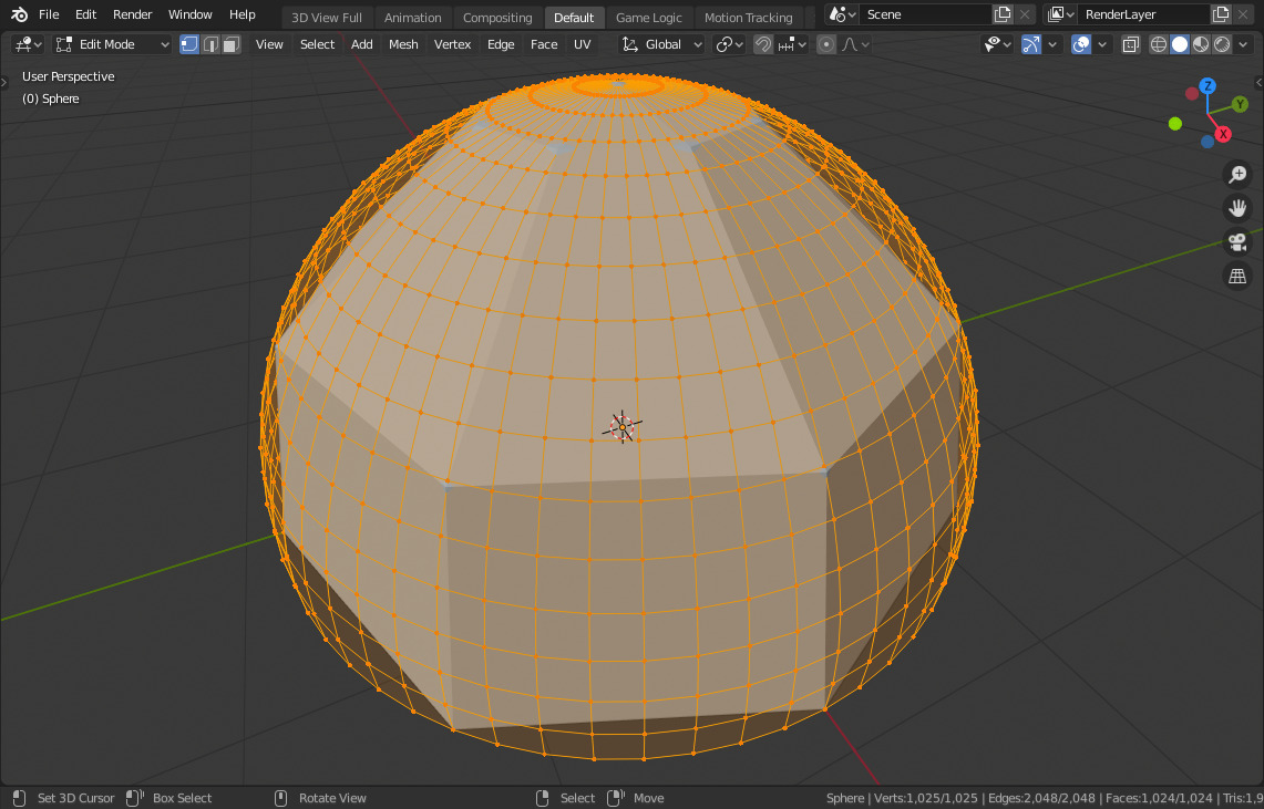
Calibration model (solid) against high resolution model (wireframe)#
Then we need to export this 3D model. With the object selected, go to ‘File > Export > Wavefront (.obj)’ menu. As export parameters, set the following:
Forward: Y forward
Up: Z up
Selection Only: true
Write Materials: false
Then browse to the directory where the configuration.json has been exported, and finalize the export with a meaningful name ( dome_hires.obj for instance).
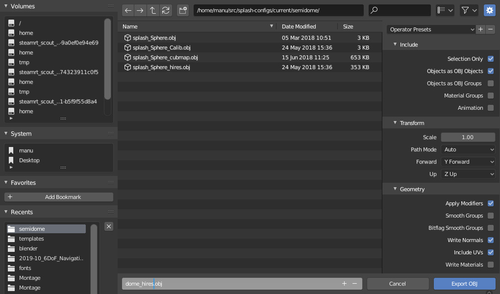
Blender configuration export panel#
Go back to Splash. In the Meshes tabulation, open the ‘mesh’ object, then set the source obj file to the newly exported file (either by manually typing the path, or by selecting it with the ‘…’ button). Save the configuration by pressing Ctrl+S.
Calibration, second round#
We can now fine-tune the calibration. Replacing the calibration model with the high definition one should already have improved things quite a bit, but chances are that there is still some work to do. There is not much to learn here, but here are a few tricks to make the projections match a bit better:
switch to wireframe mode, as it is easier to see the defaults in this mode.
for each camera, select the existing points and move them. If possible, Splash will recompute the calibration automatically. If not you can force Splash to do it by pressing Ctrl+C while hovering the view.
if some areas of a projection has no calibration point, add at least one there.
try to keep the distance between the vertices and their associated cross as small as possible. The larger the distance, the worst the calibration is from a geometric point of view.
If you have the feeling that this is as far as you can go, this is the time to use some warping. This is usually the case with projection surfaces which are far from perfect, like inflattable domes and such. The warping abilities of Splash can be found in the Warps tabulation, and work as follows:
select a camera: a lattice appears on it, each intersection being a point which can be moved,
select a point of the lattice, and move it with the mouse or the arrow keys: the view is altered accordingly,
use this to better match areas between overlapping projectors.
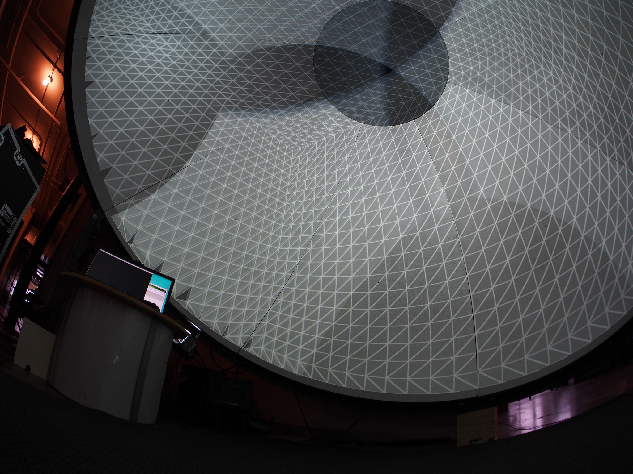
High definition dome, not blended#
Lastly, when the calibration seems correct, we can activate the blending of the video-projectors. This is the easy part: press Ctrl+B (or click on the ‘Compute blending map’ button in the ‘Main’ tabulation). Also, don’t forget to go back to textured mode with Ctrl+T.
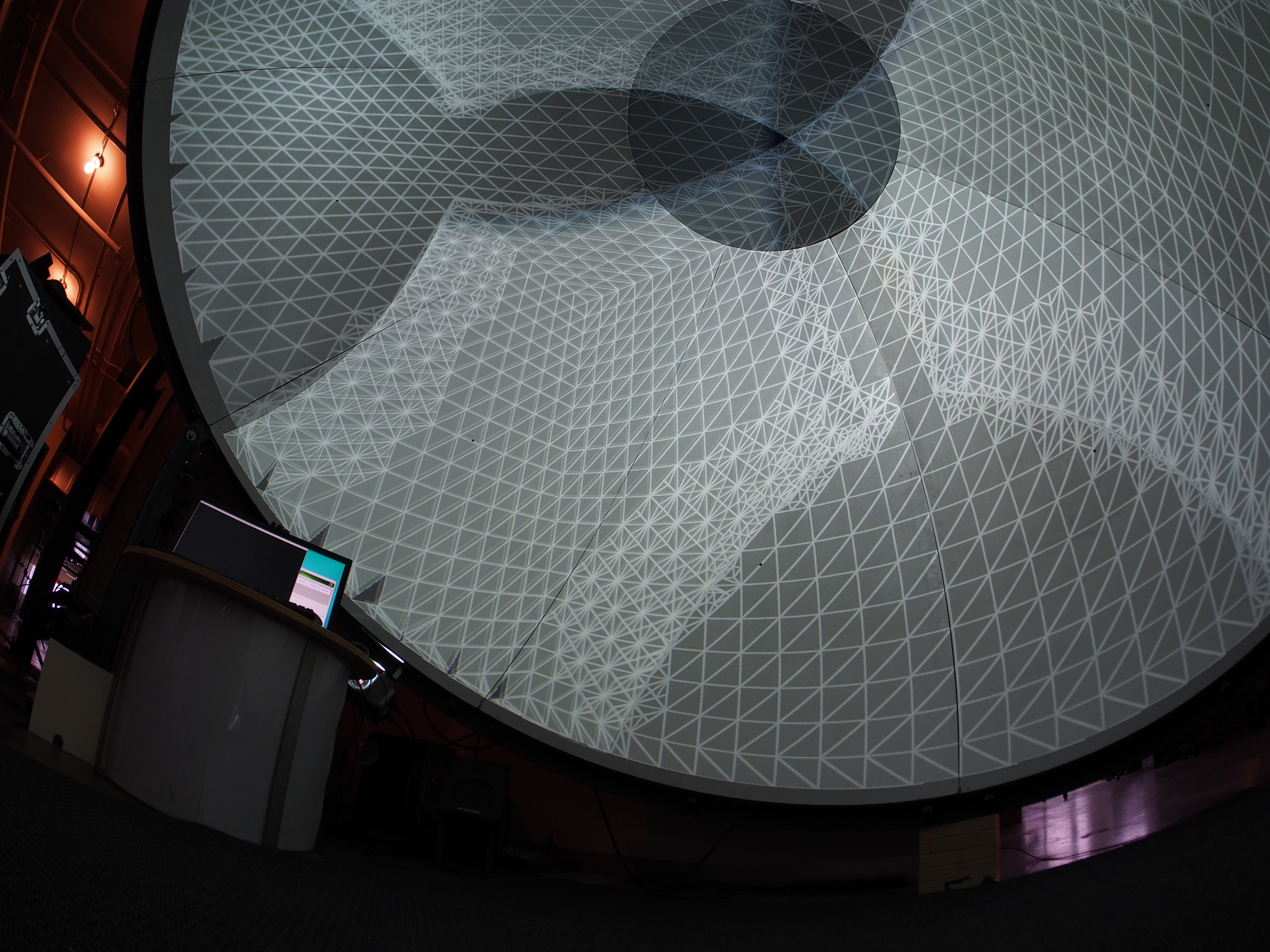
High definition dome, blended#
Load some video contents#
The final step is to replace the static texture used previously with a film. Still in Splash, go to the Medias tabulation. There you have a list of the inputs of your configuration and you can modify them. Select the only object in the list, that change its type from “image” to “video”. Next, update the “file” attribute with the full path to a video file.